modem manufacturer: SCADA applications for modem data communication modems Mexico, South and Central and Latin America AmericaSpanishChinese
Data-Linc modems, tech support, industry alliances, sales channels, trade shows, informationIndustriesHomeAbout usNewsSales ChannelsPartnerships/alliancesTechnical ServicesProducts
product indicatorList of Antennas and CablesNET620Ñ Serial to Ethernet BridgeList of Wire modemsList of Wireless modems
CIX6500- 2.4 GHz Communication Interface I/O ExtenderCIX6400- 900MHz Communication Interface I/O ExtenderDSSS High-Speed 2.4GHz OFDM modemDSSS High-Speed 900MHz OFDM modemIndustrial Wireless Ethernet FHSS 900 MHz radio modemIndustrial Wireless Ethernet FHSS 2.4 GHz radio modem802.11b WiFi Compliant 2.4 GHz DSSS Wireless PCMCIA Card Modem802.11g/b WiFi Compliant 2.4 GHz DSSS Wireless PCMCIA Card ModemIndustrial Wireless Serial FHSS 900 MHz radio modemIndustrial Wireless Ethernet FHSS 900 MHz radio modemIndustrial Wireless Ethernet chassis mount 900 MHz radio modemIndustrial Wireless Ethernet High Speed Broadband 900 MHz radio modem900 MHz Industrial Wireless Discrete/Analog Wireles Multiplexer and Signal Conditioners 900 MHz Industrial Wireless modemIndustrial 900 MHz Wireless discrete/analog I/O extenderIndustrial Wireless Serial FHSS 2.4 GHz radio modemIndustrial Wireless Ethernet FHSS 2.4 GHz radio modemIndustrial Wireless Ethernet chassis mount 2.4 GHz radio modem2.4 GHz Industrial Wireless Discrete/Analog Wireles Multiplexer and Signal Conditioners Industrial Wireless Ethernet FHSS 2.4 GHz ETSI CE Mark802.11b WiFi Compliant 2.4 GHz DSSS Wireless PCMCIA Card Modem

Material handlinghydro-electric powerOil rig drillinggas pipelineminingforestry logging


Wireless Modems:
SRM, FastLinc & PlantLinc Families


FastLinc FAQ

Smart Spectrum FAQ

SRM FAQ

Wireless FAQ

Antennas and Cables FAQ


See also

See also Technical Services:

Articles
Frequency Hopping Spread Spectrum (FHSS)

Installation:
Antennas

LincViewTM OPC
Configuraion Quick Start Guide

Download a printable PDF (341 KB) version of this LincView OPC Quick Start Guide

LincView OPC is a software application that allows users to monitor Data-Linc SRM Family radio diagnostics in a point-to-multipoint network. LincView OPC allows easy detection of network problems with radios in the network and user selectable warning or alarm conditions to alert the user of problems in the radio network.

Requirements

  • A Windows based PC (running Windows 98, NT 4.0, or later).
  • A PC with a network connection for the OPC server.
  • A PC connection to a SRM diagnostics Master modem in multipoint mode.

Connection options

  • PC with an available RS-232 port (serial connection).
    Note: SRM must have a secondary serial port/diagnositc port.
  • PC with an Ethernet connection (UDP connection).
    Note: SRM Ethernet modem only.
  • PC with an Ethernet connection and a terminal server (TCP connection). Note: SRM must have a secondary serial port and connection to the
    terminal server.

Installing LincView OPC

  • From the included CD run “(CD drive letter):\Software\LincView OPC 2.2.0\setup.exe”.
  • Follow the on screen instructions from the install program.
  • LincView OPC is now installed.

Connecting the Radios to the PC

To establish a connection between LincView OPC and the network, the radio must be connected via serial, UDP, or TCP:

A. Serial Port Connection: This is a direct connection from the serial diagnostics port to the serial port of the PC. For the SRM6000/SRM6100 uses the optional diagnostic connection on the rear panel and the SRM6210E/SRM6310E/SRM7210E uses the option side panel connection. The SRM6220/SRM6320 uses the included front diagnostics connection.
1. Plug in a straight through DB9 cable from the diagnostics port of the multipoint Master modem to the serial port of the PC (COM1 to COM20 can be used).
2. Set “Diagnostics” to a value of 1-63 (how often diagnostic data is sent— the lower the number, the more frequent data is sent). (Radio parameter, to change using terminal emulator, menu (5) Multipoint Params, then (B) diagnostics).

B. UDP Connection: This is a remote connection through the LAN port of an Ethernet Master modem. This connection is only available on the SRM6210E/SRM6310E and the SRM6220/SRM6320.
1. SRM6210E/SRM6310E/SRM7210E
Using ConfigLinc
Using Config-Linc_E.exe the Data-Linc Group Ethernet configuration software utility to configure the Ethernet multipoint Master modem:
a. Run “(CD drive letter):\Software\Config-Linc-E 1.01\Config-Linc_E.exe”
b. Select the product to configure (SRM6210E,SRM6310E, or SRM7210E).
c. Select the Comm Port (1 – 4).
d. Select “Read From Radio” button.
e. Follow the prompt and press the config button. The “Advanced Config” options are viewable.
f. Set “Diagnostics” to a value of ‘129’ the Ethernet Diagnostics options dialog box will popup.
g. Set the IP address for the Master radio. Press “OK” button when done.
h. Select “Program Radio” button to save changes to the radio.
i. Follow the prompt and press the config button.
Hardware Settings
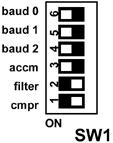
The Master radio settings are changed to proper diagnostics mode. The Ethernet I/O interface board requires a dipswitch change to enable compression to allow the UDP packets out the Ethernet port. (Does not apply to SRM6220/SRM6320).
a. Remove the end panel opposite the antenna on the modems and switch SW1-1 (labeled cmpr) to the “ON” position as shown in the figure to the right.
b. Replace the end panel on the modems.
Note: All of the modems in the network must have compression set to send proper Ethernet data.
2. SRM6220/SRM6320
Using SetLinc Utility
a. Run “(CD drive letter):\Software\..”
b. Connect to radio to configure and then select Ethernet or Serial and follow the directions.
c. Set an IP address and set the diagnostics mode under Advanced to ‘129’ and program the radio.
d. Connect the Master radio to the Ethernet network.
e. Connect the PC to the same Ethernet network.

C. TCP/IP Connection: This is a remote connection through a terminal server device to the serial diagnostics port on the multipoint Master modem.
1. Set “Diagnostics” to a value of 1-63 (how often diagnostic data is sent, lower is more frequent). (Radio parameter, to change using terminal emulator, menu (5)Multipoint Params, then (B) diagnostics).
2. Setup the terminal server to 115200-baud rate, 8/N/1 parity.
3. Setup the IP settings for the terminal server, based off the manufactures setup parameters.
4. Connect a straight through DB9 cable from the serial diagnostics port to the serial port on the terminal server.
5. Connect the terminal server to the Ethernet network.
6. Connect the PC to the Ethernet network.


LincView OPC Setup:
1. Run LincView.exe from the desktop shortcut or locate LincView in the start menu.
2. Select a network file (.NWF) from the dialog box or create a new one by typing in the file name.
3. Choose the “Alerts & Diag Settings” tab to configure the type of connection.
4. Choose the “Connection & Polling” tab in this section.
A. Serial Port Connection—Select the Serial port number that is connected to the Master modem from the PC under “Connection to Master”
B. UDP Connection:
1. Select UDP under “Connection to Master”.
2. Set the IP address of the UDP Master modem.
3. Set the port number to connect to.
4. Put 1234 in the password field, but do not put a password in the radio.
C. TCP/IP Connection:
1. Select TCP/IP under “Connection to Master”.
2. Set the IP address of the terminal server connected to the Master modem.
3. Set the port to the terminal server port number to connect to.
4. Return to the “Network & Radio Status” tab the system will start running and updating radio statistics.

For more detailed instructions for LincView OPC, please refer to the Users Guide or contact Data-Linc Group Technical Support.

Technical Support
Data-Linc Group maintains a fully trained staff of service personnel who are capable of providing complete product assistance. They can provide you with technical, application and troubleshooting, parts and warranty assistance. Our technical staff is based in Bellevue, Washington USA and may be reached at:
Phone: 425-882-2206 Email:

Product Warranty
Data-Linc Group warrants equipment of its own manufacture to be free from defects in material and workmanship for one year from date of shipment to original user. Data- Linc Group will repair or replace, at our option, any part found to be defective. Any part claimed defective must be returned to Data-Linc Group, transportation prepaid, with a return material authorization (RMA) number. Contact Technical support or the corporate office to request an RMA number for part to be sent to the factory for repair.

PN 163-09935-001 07/09
Specifications subject to change without notice
Top of Page ^

Products

Features & Benefits | Focus Item | Product Selection Guides | Catalog | PDF Library | Order Information | FAQ
Tech Resources

Engineering Specifications | Articles & Technical Papers | Installation Information
Partners

GE Fanuc | Omron | Rockwell Automation | Schneider Electric | Siemens | Technology Partners
Industries

Security | and other industry application notes and diagrams
Sales Channels

Distributors | System Integrators | OEMs
News

Tradeshows and Events | Press Releases | Newsletters
About Us

Overview | Jobs/Employment | Office Locations/Contact Information

spacerChinesespacerEspañol

spacer
Data-Linc Group
3535 Factoria Blvd. SE, Suite 100 • Bellevue, WA 98006 USA
Tel (425) 882-2206 • Fax (425) 867-0865 •

© 1996-2009 Data-Linc Group. All rights reserved.
0907013