DATA-LINC Group
Antenna Dimensions & Installation Guidelines

900 MHz antenna versions shown here, for 2.4 GHz antenna dimensions, please contact:
DATA-LINC GROUP
Phone: (425) 882-2206
FAX: (425) 867-0865 or
address

OMNI DIRECTIONAL
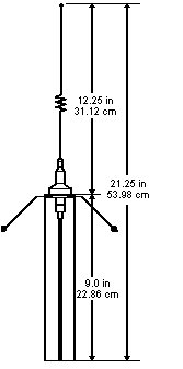
ANTENNA DIMENSIONS


omni directional antenna diagram

SRM6000 OMNI DIRECTIONAL ANTENNA
MOUNTING BRACKET DIMENSIONS

(Click here to open a full size view.)

omni directional antenna mounting bracket diagram

Download a printable pdf (2.2MB) version of the omni directional antenna (3dB and 5 dB) data sheet.
To read pdf files you need to have Adobe Acrobat Reader installed on your PC.

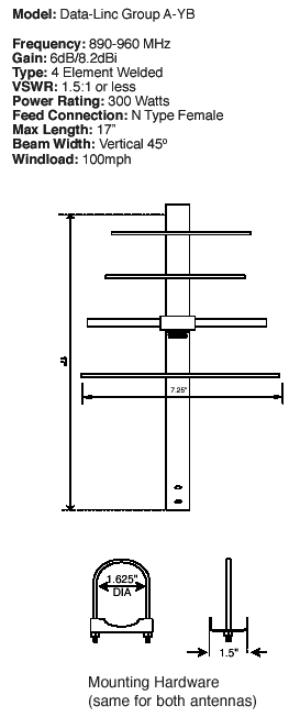
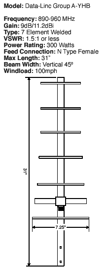
902-928 YAGI
ANTENNA DIMENSIONS

902-928MHz Yagi antenna diagram902-928MHz Yagi antenna diagram 2

P/N 155-09966-002A

Download a printable pdf (152K) version of the Yagi antenna data sheet.
To read pdf files you need to have Adobe Acrobat Reader installed on your PC.

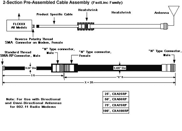
Antenna cable assembly notice

In an effort improve the versatility and convenience of our products, Data-Linc Group has made a change in the connector configuration of the antenna cable assemblies that we ship as standard product. These changes are indicated by new model numbers. Customers requiring the old style configurations for existing systems may still order any of the old assemblies under their old model numbers.

The changes involve all multi-piece coaxial cable assemblies. Any and all coax junctions using "N" type connectors will now have the male connector on the modem side of the junction with the contacts facing up towards the antenna. All "N" connectors facing down, including the one on the antenna, will be female.

These changes are intended to allow end users to easily construct a transmission line to meet their needs. Any RF or electrical accessories that are intended to be part of the transmission line should be ordered with female "N" connectors pointing towards the modem and male "N" connectors facing the antenna. In the absence of this option adapters should be ordered as needed to meet this requirement.

If surge protectors are to be installed in the transmission line, the end user should take care to order all the coax sections required to properly locate the surge protector in accordance with the manufacturer’s instructions.

2-section pre-assembled cable  assembly diagram

Also Note: CX150, CX200, CX250 not recommended for 2.4GHz use.

Installation Guidelines

1. High and Free. Not only is the relationship between the antenna and the earth improved by mounting it higher (resulting in better range), but the problem of interrupting the line-of-sight is reduced. Avoid mounting right next to solid objects (walls, buildings, towers, or girders). The resulting reflected radio energy causes drastically reduced efficiency. A minimum of six feet is a good general rule.

antenna installation guide diagram 1

2. Other Electrical Things Should Not Be Close. Not only do you want to stay away from sources of electrical noise (power lines, electrical motors, solenoids, high power radio signal sources, or any high-voltage power usage), but you want to avoid the possibility of electrical shock, which can be fatal.
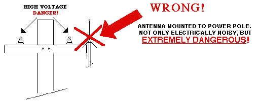
antenna installation guide diagram 2

3. Line-of-Sight means "You Can See It From Here!" Operating in the frequency range that it does, the radio carrier is really deflated by obstructions that block the signal path. The only way to assure constant, solid communications is to make sure that the antennas are actually visible to each other. This means that if you took a laser and pointed it from one antenna to the other antenna, the far antenna would have a little red laser dot on it.
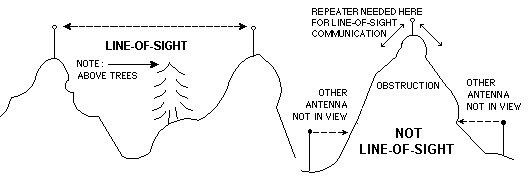
antenna installation guide diagram 3

4. If You Have a Yagi Antenna, You Have To Point It The Right Way. In order to have "Gain," a Yagi antenna takes its signal strength from all around and points it in one general direction. This makes the Yagi "Directional." That means that it has to be oriented one particular way so the radio signal is pointed toward the antenna of the device with which you want to communicate.

Yagi antenna direction of radio energy diagram

5. If You Have An "Omni" (Omnidirectional) Antenna, mount it pointing up. The Omni antenna is designed to be usable from any direction (hence its name) As a result, it doesn´t have the straight-line range of the Yagi, but because it distributes its radio energy in more of a donut shape, be sure you s that the main part is oriented straight up and down, with the feed line at the bottom. In the base, there are four angled wires, called "ground radials" which should be rotated until they are angled downward, for the best efficiency.
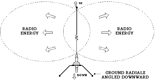
omni directional antenna radio energy diagram

For further information, please contact
DATA-LINC GROUP
Phone: (425) 882-2206
FAX: (425) 867-0865 or
address

Content by DATA-LINC GROUP
©1996-2008 All rights reserved.
080603