|
|
||||
|
||||


|
|
Articles and Technical PapersAdding Wireless Metrics to your HMITo keep it simple, a single human interface for application monitoring and control is best. Wireless radio networks or wireless network extensions are common today and often require separate human interface for monitoring and control. Using Data-Linc Group's LincView OPC diagnostic software for the SRM series of wireless products it is now possible to integrate application and wireless information into an HMI and thus achieve a single seamless operator interface. As an OPC server, LincView OPC provides over 50 real time metrics about each radio and its RF path that can be used by an OPC client such as RSView32. A typical implementation will require your OPC client, a newer SRM master radio with firmware version 2.xx or 3.xx (shipped since 2003), LincView OPC software (available at no charge), and depending on usage the master radio may require a field installable diagnostic port (less than $100 from Data-Linc). Let's build a specific solution using these metrics. Figure 1 is an RSView32 graphic of Clearwater's NetLinx Ethernet with SRM6210E radios for wireless connection of Town Hall, West Tank, East Tank, and Blue Mountain Pump Station. At Town Hall is the master radio and workstation with RSView32 and LincView OPC. |
||
|
Figure 1: Clearwater's NetLinx Ethernet with SRM6210E radios connects Town Hall, West Tank, East Tank, and Blue Mountain Pump Station with the Master radio and workstation with RSView32 and LincView OPC at Town Hall. (Click image for enlarged view.) For the first time only the following steps are performed. LincView can use various methods to communicate with the master radio and since we are using Ethernet, we'll use the UDP method which requires each radio to have its internal compression switch set on. Additionally, and only in the Master radio configuration, the “Diagnostics” parameter set to 129, the “IP Address” set as appropriate for your network (192.168.7.69 in our case) and the “Port Address” set to 4131 as shown in part on Figure 2. |
|
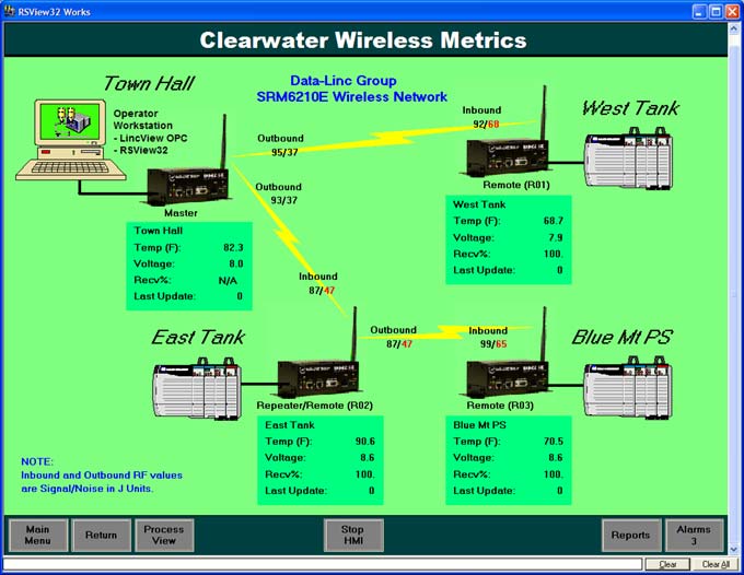
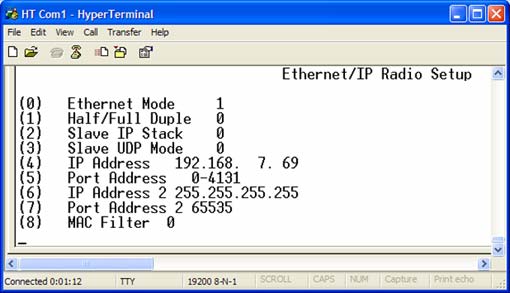
Figure 2: LincView screen shot showing the UDP method (one of a number of method options) to setup communication with the Master radio. Next LincView is started, a network file created, the OPC server named, and the Master radio IP Address and Port Address entered (Figure 3). |
|
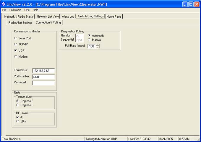
Figure 3: With LincView started, create a network file, name the OPC server and enter the Master radio IP Address and Port Address. (Click image for enlarged view.) LincView OPC is now “Talking to Master on UDP” as shown is Figure 4. Note too, each radio can be named by right clicking on the radio call number in tree view (on the left side of the screen). |
|

Figure 4: Screen showing LincView OPC "talking" to the Master on UDP. (Click image for enlarged view.) To use LincView OPC in RSView32, add a new OPC Server node and use the OPC Server Browser to select the LincView OPC server name (Figure 5).
Figure 5: For RSView32, add a new OPC Server node and use the OPC Server Browser to select the LincView OPC server name. (Click image for enlarged view.) Then, for each desired radio metric, a Tag must be created in the Tag database and the OPC address browser used to select the desired radio metric as shown in Figure 6. |
|
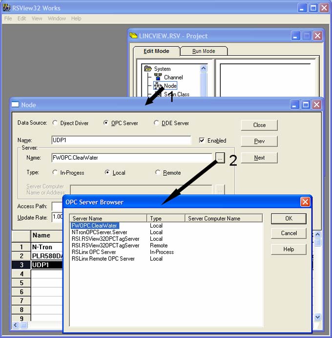

Figure 6: For each additional radio metric, create a Tag in the Tag database and the OPC address browser used to select the desired radio metric. (Click image for enlarged view.) As with other database tags they can be used on any graphic, archived for historical reference, and used to generate alarms. The graphics screens are constructed using your familiar practice. Seamless integration of both application and wireless data offer many benefits including a single user interface that can be used for fast application/radio problem identification resulting in reduced down time. For your convenience LincView OPC also presents a graphical interface of all available diagnostic information. Please contact Data-Linc Group Technical Support at 425-882-2206 or
|
|
| ^ Top of Page ^ | ||
|
|
||
| Products |
Features & Benefits | Focus Item | Product Selection Guides | Catalog | PDF Library | Order Information | |
| Tech Resources |
Engineering Specifications | Articles & Technical Papers | Installation Information | |
| Partners |
GE Fanuc | Omron | Rockwell Automation | Schneider Electric | Siemens | Technology Partners | |
| Industries |
Security | Traffic | and other industry application notes and diagrams | |
| Sales Channels |
Distributors | System Integrators | OEMs | |
| News |
Tradeshows and Events | Press Releases | Newsletters | |
| About Us |
Overview | Jobs/Employment | Office Locations/Contact Information | |
|
|
||
| © 1996-2015 Data-Linc Group. All rights reserved. | ||
| 071030 |