|
||||
|
News & Events
|
Water District's SCADA System Goes With the FlowSt. Augustine's monitoring and control system is heaven sent.
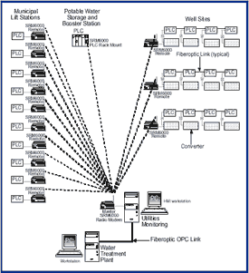
SAPW designed a state-of-the-art SCADA system to monitor and control 12 off-site wells, 10-12 critical municipal lift stations and a water repump station that supplied one of the fastest-growing communities in the City. Bob Spitz of Control Systems Automation in Elkton, Florida was contracted as consultant and project integrator. Initially, the hardware was chosen for the plant and pumping station. Radio equipment was then selected and Data-Linc wireless serial modems were chosen:
Spread Spectrum, frequency-hopping technology. Wireless, with an operating range of up to 20 miles with line-of site. Proven compatibility with major automation communication products and ease of integration. Reliability and technical specifications (based upon Control Systems Automation’s research). The lift station RTUs were designed and built, utilizing a wireless SRM6000 radio connected directly to a PLC via the communications port. DC power supplies provided the required power, and were backed up with sealed gel batteries. An auctioneering-diode circuit switches from line power to battery in the event of a power loss. Each of these RTUs monitors approximately 10 I/O points including levels, pump failure alarms, cycle-counters, pump run status and motor elapsed time meters. These RTUs communicate to an SRM6000 base station at the central utilities monitoring center. Here, the data is polled by using the DF-1 Polling Master driver— one of the customizable drivers contained in the software. This driver is configured to poll data from each PLC through the remote SRM6000 according to the addresses entered in the driver’s polling list. The speed is 19,200 baud. Next, the well field RTUs were built with a similar design, except for the field I/O and local fiber optic network. A local fiber optic network of 18,000 feet in length allows protocol converter modules to poll four PLCs, each using their native RS-485 protocol. The base radio polls each of the 1770 KF-3 modules and their connected PLCs by address, contained in the same polling list as the list station RTUs. A fiber network was used to concentrate the data passing to and from the PLCs and get the data to a non-wooded site. From here, it communicates to the base station via radio. The well field is approximately 10 miles from the base station in an area heavily wooded with many 80 ft+ pine trees. This I/O, including pump status, pump failures, run timers and pressure measurement is sent back to the host software system. In addition, a diesel-powered generator is monitored and remote start/stop control of the pumps is used by operators for controlling the total plant raw water flow. Prior to this project, daily check-up and pump starting was performed by a 25 minute drive to the well field every time something had to be checked or a pump had to be started or stopped. The pump station follows a similar scenario, although the control was a bit more complex because it utilized variable speed drives to control domestic water header pressure. Here, the RTU is communicating to a SRM6000 radio back to the base. All equipment in the block diagram on the cover page is functional and operating successfully. Control Systems Automation is now in the process of adding another 8 lift station RTUs and possibly two more wells this year as the water demand grows. No "middle" design engineer was used; acting as a designer/integrator, Bob Spitz worked directly with City staff to implement the new system, saving approximately $150K in traditional engineering and construction fees. Total project budget to date was $275K. Central and north-central Florida is renowned as a lightning haven, however there has been no failure of any communications equipment due to lightning. Both the PLC manufacturer and Data-Linc application engineers supported Control Systems Automation throughout the project. According to Bob Spitz, "Data-Linc was very helpful in solving problems that came up during the design and implementation phases simply by providing knowledgeable people on the other end of the telephone." Bob continued, "... the SRM6000 radios have provided exactly what I was seeking, a virtually transparent mode of communication over radio. The best communication gear is the kind that, once in service, you don’t know it’s there." Special thanks to Bob Spitz, consultant for Control Systems Automation, for contributing this article. For additional information on this system, contact Bob at 904.669.7665 or email beach13@aug.com. ^ Top of Page ^ Data-Linc's SRM Family adds two new membersThe new SRM6210E and SRM6310E license-free, frequency hopping spread spectrum Wireless Ethernet Radio modems offer a smaller footprint (2.45"H X 3.38"W x 6.3"L), flexible mounting (movable brackets and optional DIN-rail mount clip) and an extended operating temperature range of -40 to 167° F (-40 to 75° C). The SRM6210E is designed specifically for the license-free 902-928 MHz ISM band while the SRM6310E is designed for the 2.4-2.4835 GHz ISM band. Both are also fully RF compatible with their counterparts, the SRM6200E and SRM6300E models. An optional diagnostics management software program (LincView) is also available for remote monitoring and maintenance. This software tool is ideal for large SCADA applications. Back to Basics: Antenna 101
Selecting the right antenna is paramount to antenna performance. One factor to consider is antenna gain. Gain is achieved at the expense of beamwidth: higher-gain antennas feature narrow beamwidths while the opposite is also true. Omni Directional The omni directional is designed for use in any direction. This antenna radiates and receives equally well in all horizontal directions. The gain of an omni directional antenna can be increased by narrowing the beamwidth in the vertical or elevation plane. The net effect is to focus the antenna’s energy toward the horizon. Omni directional antennas with different gains are used to improve reception and transmission in certain types of terrain. A 0 dBd gain antenna radiates more energy higher in the vertical plane to reach radio communication sites that are located in higher places. These are better suited in mountainous and metro-pol it an areas with tall buildings. A 3 dBd gain antenna is the compromise in suburban and general settings. A 5 dBd gain antenna radiates more energy toward the horizon compared to the 0 and 3 dBd antennas to reach radio communication sites that are further apart and less obstructed. The 5dB is best suited in deserts, plains, flatlands and open farm areas. Directional Antennas Directional antennas focus energy in a particular direction. Directional antennas are used in some base station applications where coverage over a sector by separate antennas is desired. Point-to-point links also benefit from directional antennas. Yagi and panel antennas are directional antennas. They must be oriented in one particular direction so the radio signal is focused toward the antenna of the device with which you wish to communicate.
One key to proper installation is height. Generally range is improved by mounting the antenna as high as possible. Avoid installing the antenna next to solid objects such as walls, buildings, towers or girders. Reflected radio energy may drastically reduce antenna performance. Six feet from any solid object, including Earth, is the rule of thumb. Avoid installing the antenna near electrical sources, such as power lines, electrical motors, solenoids, high power radio signal sources or nay high-voltage power usage). Aside from reducing antenna performance due to electrical noise, there is always the possibility of electrical shock. Line of sight (LOS) is an imaginary "straight line" from point A to point B. The radio carrier is deflated by obstructions that block the signal path. To ensure constant, solid communications, antennas should be visible to each other. Again, omni directional antennas should be mounted as high possible as shown above. The coax cable can be anchored by using cable ties or tape. The four angled wires, called ground radials, should be rotated until they are angled downward. This increases antenna efficiency. The Yagi antenna should be mounted so the cross sections attached to the central spine (or elements) are oriented vertically as depicted in the photo to the left. The central spine should be pointed toward the other antenna. The Yagi antenna should never be mounted vertically (shown right) as radio energy is radiating upwards rather than at the receiving antenna. Data-Linc offers an assortment of antennas— each designed to enhance performance For more information, contact your local distributor or Data-Linc Group at (425) 882-2206 or email sales@data-linc.com. ^ Top of Page ^
Bridging information networks |
||||||||||||||||||||||||||||||||||||||||||||||
| ^ Top of Page ^ | ||
|
|
||
| Products |
Features & Benefits | Focus Item | Product Selection Guides | Catalog | PDF Library | Order Information | FAQ | |
| Tech Resources |
Engineering Specifications | Articles & Technical Papers | Installation Information | |
| Partners |
GE Fanuc | Omron | Rockwell Automation | Schneider Electric | Siemens | Technology Partners | |
| Industries |
Security | and other industry application notes and diagrams | |
| Sales Channels |
Distributors | System Integrators | OEMs | |
| News |
Tradeshows and Events | Press Releases | Newsletters | |
| About Us |
Overview | Jobs/Employment | Office Locations/Contact Information | |
|
|
||
| © 1996-2009 Data-Linc Group. All rights reserved. | ||
| 071203 |


